
Drive Pulleys

Drive Pulleys
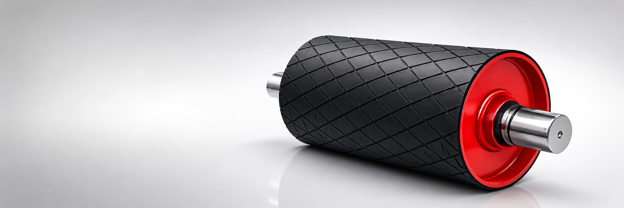
Drive pulleys are manufactured to transmit power reliably and efficiently under continuous operating conditions. Moventis drive pulleys are supplied with optimized shaft, lagging, and bearing configurations to ensure maximum traction, long service life, and stable conveyor operation.
| Parameter | Available Options / Range | Remarks |
|---|---|---|
| Pulley Type | Drive Pulley | Head / Drive station |
| Pulley Diameter (Ø) | Ø250 – Ø1000 mm | Custom diameters available |
| Face Width | According to belt width | Belt width + edge clearance |
| Shaft Diameter (Ø) | Ø40 – Ø180 mm | Selected based on pulley size & torque |
| Shaft Type | Solid shaft | Keyed as standard |
| Shaft Material | C45 / AISI 1045 | Higher grades on request |
| Shell Material | Carbon Steel (S235 / S355) | Machined & balanced |
| Lagging Type | Rubber lagging / Ceramic lagging | Duty dependent |
| Lagging Pattern | Plain / Diamond / Chevron | Improves traction |
| Lagging Thickness | 8 – 20 mm | Based on belt tension |
| Lagging Bonding | Cold bonded / Hot vulcanized | Hot vulcanized for heavy duty |
| Bearing Type | Spherical roller bearings | Long service life |
| Bearing Housing | SN / SNL Plummer block | Standard |
| Balance Grade | Static / Dynamic | ISO balance standards |
| Design Standard | DIN / ISO | Customer standards possible |
| Operating Temperature | -20 °C to +80 °C | Extended range on request |
| Application Duty | Light / Medium / Heavy duty | — |
About Drive Pulleys
Drive pulleys are the primary power transmission component of any belt conveyor. Connected to the motor and gear unit via a shaft and coupling, the drive pulley transfers torque to the belt through friction between the belt backing and the pulley surface. The magnitude of this friction force — and therefore the maximum transmittable torque — depends on the belt tension ratio, the wrap angle, and the friction coefficient between belt and pulley surface.
Lagging is applied to the drive pulley surface to increase the friction coefficient and protect the pulley shell from abrasive wear. Rubber lagging is the standard choice for dry and moderately wet applications, providing a friction coefficient of 0.35–0.40. Ceramic lagging, with embedded ceramic tiles in a rubber matrix, raises the effective friction coefficient to 0.40–0.50 and is specified for wet conditions, high-tension drives, or applications where belt slip cannot be tolerated.
Pulley construction centres on the welded steel shell, which is machined to tight diameter tolerances to ensure even load distribution across the belt width. End discs connect the shell to the shaft via interference-fit hubs. The shaft is sized for the combined bending and torsional loads from belt tension and drive torque, with shaft deflection limited to prevent premature bearing and seal failure.
Bearing selection for drive pulleys targets L10 life exceeding 40,000 hours under rated load conditions. The bearing housing design must accommodate the radial loads from belt tension and any axial loads from belt tracking, while maintaining correct shaft alignment. Grease-lubricated sealed bearings are standard; oil bath lubrication is used in very heavy-duty or high-temperature applications.
Frequently Asked Questions
Lagging increases the friction coefficient between the belt and pulley surface, which determines the maximum torque that can be transmitted without belt slip. It also protects the pulley shell from abrasive wear and helps the belt track centrally. Without lagging, the smooth steel surface has a much lower friction coefficient — particularly when wet — making belt slip a constant risk under load.
Ceramic lagging is specified when moisture is present in the loading zone or on the belt surface, when the required belt tension ratio is high (T1/T2 > 3.5), or when the consequences of belt slip are severe. The embedded ceramic tiles maintain effective grip even when wet, giving a consistent friction coefficient that rubber lagging cannot match in wet conditions.
Wrap angle is the arc of belt contact around the drive pulley, typically 180–240° depending on the drive arrangement. The minimum wrap angle required is calculated from the belt tension ratio (T1/T2) and the friction coefficient of the lagging. Higher tension ratios or lower friction coefficients require greater wrap angles. Snub pulleys are used to increase wrap angle when the natural contact arc is insufficient.
Belt slip occurs when the drive torque demand exceeds the maximum friction force available between the belt and pulley. Common causes include: insufficient wrap angle, wet or contaminated lagging surface, worn lagging below minimum thickness, incorrect belt tension, or sudden overload during starting. Soft-start drives (VFD or fluid couplings) reduce peak starting torque and significantly lower slip risk.
Minimum drive pulley diameter is determined by the belt carcass type (EP, NN, or Steel Cord), strength class, and ply count, following ISO/DIN lookup tables. This minimum is then stepped up based on duty cycle, operating environment, start mode, and required wrap angle to arrive at the recommended diameter. Using a larger-than-minimum diameter extends belt carcass life at the pulley contact zone.
Drive pulleys require periodic inspection of lagging condition (wear, cracking, delamination), bearing lubrication or regreasing, shaft seal inspection, and check of pulley-to-shaft interference fit. Lagging should be replaced when wear reaches the minimum thickness or when ceramic tiles show significant loss. Bearing replacement intervals depend on duty — typically 3–5 years in medium-duty applications.