
Vibrators

Vibrators
Interactive Vibrator Selector
Find the right vibrator specification for your application
About Vibrators
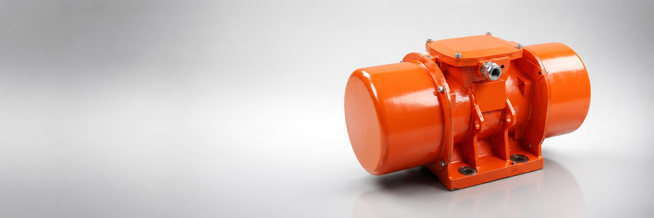
Industrial vibrators are used to initiate and maintain controlled material flow from storage and feeding equipment — hoppers, bunkers, silos, and transfer chutes — where gravitational flow alone is insufficient to overcome friction, cohesion, or bridging.
The vibrating force required depends on the active mass of material in contact with the vibrated surface, the material’s flow resistance (expressed as a fraction of gravitational acceleration), and the geometry of the outlet. Harder-to-flow materials — wet fines, large lumps, sharp-edged aggregates — require higher excitation forces and may need multiple vibrators to achieve uniform flow across the outlet area.
Electric vibrators operate by rotating eccentric masses at the supply frequency (50 or 60 Hz). The centrifugal force generated is proportional to the eccentric mass and the square of the rotational speed. This makes frequency selection important: at 50 Hz, the vibrators produce higher force at lower power; at 60 Hz, higher frequency suits applications requiring faster flow response.
Wall thickness determines the structural compliance of the equipment — thinner walls deflect more, transmitting vibration energy more efficiently into the material mass. Heavier wall sections require higher excitation force to achieve equivalent material activation. Outlet size affects how much material can actively bridge: small outlets with cohesive fine materials present the highest bridging risk and typically require the greatest force-to-mass ratio.
Frequently Asked Questions
The force is calculated from the active material mass (volume × density × application ratio), the material’s flow resistance factor (g-factor, increased for difficult conditions), and correction factors for wall thickness, outlet size, and duty cycle. The result is the minimum centrifugal force the vibrator must produce to initiate and maintain flow.
Bridging occurs when material particles interlock or cohere across the outlet opening, forming an arch that prevents flow. It is most common with fine, wet, or sticky materials in small-outlet applications. Wet / Sticky condition and small outlets are the primary risk factors — the calculator flags these cases and increases the recommended force accordingly.
Two vibrators are recommended when the calculated total force exceeds 8 kN. At this level, a single vibrator would need to be excessively large, creating structural stress concentrations. Two units mounted symmetrically distribute the load and provide more uniform excitation across the equipment walls.
Vibrator speed is directly tied to supply frequency — at 50 Hz, the eccentric mass rotates at 3000 rpm (2-pole); at 60 Hz, at 3600 rpm. Higher frequency increases force for the same eccentric mass but also increases bearing wear rates. 50 Hz is standard in Europe and most of Asia; 60 Hz in the Americas and parts of Japan.
Vibrators should be mounted on the hopper sidewalls, above the outlet zone, at an angle that directs vibration energy toward the material mass. Mounting plates must be reinforced to prevent fatigue cracking from the continuous cyclic load. Anti-vibration mounts should be used between the hopper structure and supporting steelwork to prevent vibration from transmitting to the conveyor frame.
Electric vibrators require periodic bearing inspection and lubrication, eccentric mass bolt torque checks, and visual inspection for cracks around the mounting plate. Bearing replacement intervals depend on duty — typically 8,000–12,000 hours under medium duty. Vibrators in wet or dusty environments require more frequent inspection of shaft seals and terminal box integrity.